
The remote automated control system (RAC) «IMPULSE»


The remote automated control system (RAC) «IMPULSE» is designed to control shipboard propulsion systems of various types:
- Diesel and diesel geared generator units (DGU);
- Propulsion and steering columns (PSC), including the "Azipod" type, and container type (with a limited angle of rotation of the gondola);
- Maneuvering device (MD) and retractable maneuvering device (RMD);
- Water jet propellers (WJP);
- Steering devices (SD).
The IMPULSE RAC system provides control of the propulsive (propulsion) complex of the vessel by issuing control signals to the executive equipment, сontrols the condition of all devices included in the ship's propulsion complex.
"IMPULSE" provides three types of control (listed according to priority):
Local – from the local control panel of the LCB board;
Remote – from one of the remote control posts;
Automatic – from third-party systems and/or Joystick System.
The local control board (LCB) is equipped with a local control panel, an LCD screen, as well as duplicate display devices and controls. The system is based on modern programmable logic controllers with high performance. The internal structure is designed according to the modular principle with the possibility of expanding and changing the number of internal modules to increase the number of input and output signals of sensors and external systems. The composition and number of remote control posts are selected based on the type of propulsion system and Customer requirements.
The system has the following advantages:
- Certified by the Russian Maritime Register of Shipping RMRS and the Russian Qualification Society RKO;
- Modular design with double internal redundancy and rich expansion possibilities;
- Support for a wide range of interfaces: RS-422/485 (Modbus, Profibus, NMEA), 4...20 mA, dry contacts;
- Collaboration with a wide range of ship systems: DP, ISU TS, APS, DDR, generalized information display, etc;
- Based on a modern high-performance PLC;
- Uninterruptible power supply with up to 30 minutes of battery life;
- Software tools for system diagnostics;
- Non-volatile error and crash log.
|
Characteristic |
Parameter |
|
Supply voltage |
main and reserve networks: 220V 50/60Hz (with automatic switching from one to another) autonomous operation mode up to 10 minutes (from the built-in battery) |
|
Built-in protection |
- for a 220 V power supply circuit – galvanic isolation up to 1500 V - for a 380 V power supply circuit – galvanic isolation up to 2000 V the inputs and outputs are galvanically isolated |
|
Input and output signals of |
Digital (interface) inputs/outputs: - RS-422/232 (NMEA) - RS-422/485 (Modbus RTU) - Ethernet Analog inputs/outputs: Signal type 4...20 mA (load max 500 ohms with galvanic isolation from each other) Logical (discrete): For signals of the "dry contact" type (24 V DC, maximum power 0.5 W), with galvanic isolation in groups) Relay: Of the "dry contact" type (30 V DC, maximum current 5 A; 250 V AC 50(60) Hz, maximum current 5 A) |
|
Power supply of third-party |
Power supply of third-party equipment (carried out through the PD device): Output voltage =24 V (up to 2 kW) Output voltage ~220 V 50 Hz (up to 10 kW) Output voltage ~3x380 V 50 Hz (up to 36 kW) |
|
Operational limitations |
|
|
Power consumption |
No more than 2200 W |
|
The degree of protection of devices |
IP44 |
|
Working temperature |
from -10 to +55 °C |
The composition of the system is determined in the order depending on the type of propulsion system and its technical characteristics. In general, the system consists of the following devices.
|
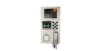
Local control board |
System-forming device. It is a metal board mounted with a built-in PLC and expansion modules. The local system control panel (LCP) is located on the front panel. LCB Manages communication with other custom ship systems (ISU, APS, RD, RSP and other systems). It is usually located in close proximity to the control object (engine room, tiller room, room of MD, etc.) |
|
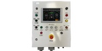
The Board of the local |
A device for controlling a diesel unit. It is a metal board mounted with a built-in PLC and expansion modules. The local control panel of the diesel unit is located on the front panel. It is usually located in close proximity to the diesel unit. |
|
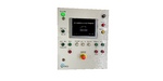
Pump engine starters |
A power board designed to perform the function of automatic reserve input (ARI), uninterruptible power supply of the control system (from the built-in battery) and power supply of third-party power equipment via the following networks: - Power supply =24V (sensors, solenoids, valves of hydraulic systems, etc.) - Power supply ~220V 50Hz (various equipment) - Power supply ~3x380V 50Hz (hydraulic pumps systems, etc.) It is a metal board mounted with built-in equipment. It is usually located in close proximity to the object of electricity consumption. |
|
Uninterruptible power |
An external uninterruptible power supply unit for the control system. Output power =24V, input power to choose from: ~220V 50Hz, ~3x220V 50Hz or ~3x380V 50Hz. It is a metal hinged board with built-in equipment and a battery. It is usually located in the immediate vicinity of the LCB. |
|
Remote control panel |
The remote control panel. It is a panel with a film keyboard, buzzer, emergency stop mushroom button and LED indicators. Designed for embedding in a cutout. The number and name of buttons and indicators are custom-made. It is usually located in the wheelhouse and/or the CPU room and other rooms. |
|
Information display unit |
It is an LCD screen with various diagonal options for embedding in the cutout. It is usually located in the wheelhouse, CPU room, navigation room and other rooms. |
|
Turn and speed control |
Azimuthal (rotary) handle for controlling the speed and angle of rotation of the actuator (WHERE, DRC, VPU). Designed for embedding in a cutout. It is usually located in the wheelhouse or the CPU room. |
|
Speed control handle |
The handle for controlling the speed of the rowing engine of the GD or the maneuvering device. Dual design options are available (for controlling two actuators) and horizontal or vertical control (for controlling the rpm of the GD or PU). Designed for embedding in a cutout. It is usually located in the wheelhouse or the CPU room. |
|
Pointer indicator |
Pointer indicators of the rpm of the GTD propeller engine or the angle of rotation of the actuator (RM, DRC, VPU, etc.). Designed for embedding in the cutout. It is usually located in the wheelhouse or the CPU room. |
|
Panoramic speed |
Indicators of the panoramic type of steering angle. Designed for installation on the ceiling. It is usually located in the wheelhouse or the CPU room. |
|
Steering wheel |
The steering wheel of the tracking control to control the steering machine. It is a steering wheel with a scale, a design for embedding in a cutout. It is usually located in the wheelhouse or the CPU room. |
|
Simple control handle |
A simple (non-tracking) control handle for steering machine control. It is a handle with discrete limit switches for turning of the steering machine (right and left), a design for embedding in a cutout. It is usually located in the wheelhouse or the CPU room. |
|
Panels for switching |
Additional panels with selector switches or with a backlight brightness control. It is usually located in the wheelhouse or the CPU room. |
|
Rotation angle sensor |
Feedback sensor for the angle of rotation of the actuator (steering machine, DRC or other devices). Options with one or two control channels and with additional limit switches are available. |
|
Actuator (actuating |
An actuator for converting an electrical signal into a mechanical movement of the control rod. It is used to control the fuel rail of a diesel unit, control gear units and other mechanical systems. It is located in close proximity to the actuator. |
The block Chart of the components of the system is determined on the order depending on the type of propulsive system and its technical characteristics. The maximum possible composition of the system's devices is shown in the block Chart.
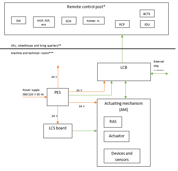
Where are marked:
- Blocks
RCP – Remote control panel (push-button indicator);
SW – Steering wheel;
MSP - Mode Switching panels;
PSP - Panels for switching posts;
BSP - Brightness switching panels;
SCH - Simple control handle;
Pointer In. – Pointer indicator of the speed of the propeller engine;
BCTS - Block (handle) for controlling turns and speed;
IDU - Information display unit (monitor);
LCB - Local control board;
PES - Pump engine starters;
LCS board - The board of the local control system;
RAS - Rotation angle sensor.
- Connections:
Green – Signals;
Red – Power supply
Notes:
* The system can include up to 5 remote controls
** Locations of remote control panels
*** Locations of LCB, AM, LCS board, PES