
Control system for the rocking calmer "SKAT-1031"
Control system for the rocking calmer "SKAT-1031"
The system is designed to control the steering devices of the ship's side rudders, maintain the specified amplitude (magnitude) and frequency (period) of the on-board pitching of a moving vessel by changing the angle of rotation of the rudder pen in the plane of the ship's midship frame.
The rocking calmer system provides operation in two modes:
-Rocking calming mode (when the ship's speed is up to 12 knots);
-Ship rocking mode (when the ship's speed is in the range from 5 to 10 knots).
On-board steerable rudders are located sideways from the outside of the vessel's hull and create a torque that counteracts the ship's side pitching or creates it, depending on the selected mode. The total number of SR is 2 pcs. (one per board).
- Power supply network parameters
The system is powered by the ship's power supply (three-phase 400 V electrical network). Deviations from the nominal values of the supply network are shown in the table below:
|
Parameter |
Deviation from nominal values, % |
Duration of short-term deviation, s |
|
|
Long-term |
Short-term |
||
|
AC voltage |
+6 -10 |
+20 -30 |
1.5 1.5 |
|
Frequency |
±5 |
±10 |
5 |
The power consumption for the system's own needs it does not exceed more than 2000 Watts (at a mains voltage of 400 V).
- The degree of protection of the system equipment-IP44.
- The communication of «SCAT-1031» with external control systems is provided by the following signals:
|
|
Analogue signals |
Digital signals |
Digital connection |
|
Inputs |
From 4 to 20 mA (resistance is not more than 200 Оm) |
24V «dry contact» |
Modbus TCP/IP |
|
Outputs |
From 4 to 20 mA (the load is not more than 500 Оm) |
24V «dry contact» (relay outputs no more than 0,5A) |
The main parameters provided by the SKAT-1031
- In terms of providing functionality:
- ship rocking mode;
- rocking calming mode;
- uninterrupted communication with external ship systems
- In terms of providing indication and EWS (emergency warning system):
- protective shutdown devices;
- control of the availability of power;
- network voltage monitoring;
- phase break control;
- protection against short - circuit currents;
- parameter control and protection of pump electric motors;
- monitoring of parameters of hydraulic system sensors;
- uninterruptible power supply CS from UPS;
- registration of SR and CS malfunctions, recording in a non-volatile log of accidents and warnings;
- issuance of fault alarms for SR and CS to local and remote control posts;
- accident acknowledgment;
- emergency stop.
- In terms of providing control:
- local control (from the buttons on the front panel of the PMS and the touchscreen of the LCD);
- remote control of the equipment (from the touch screen of the control panel and external ship's control panels);
- emergency stop from any control station;
- priority of control from the local control post.
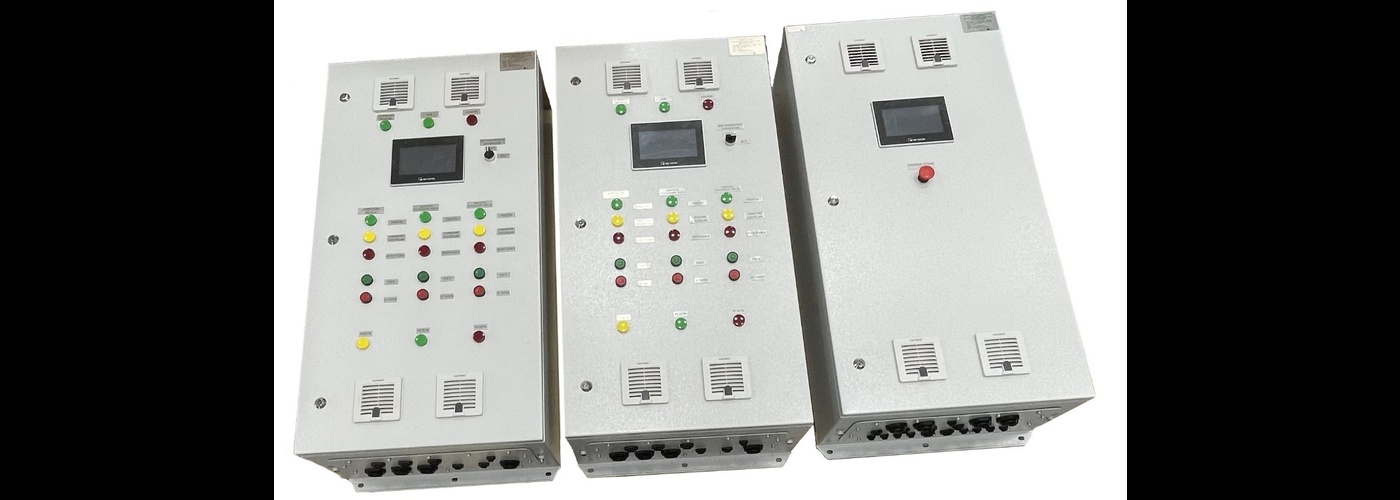
SC "Skat-1031" consists of the following parts:
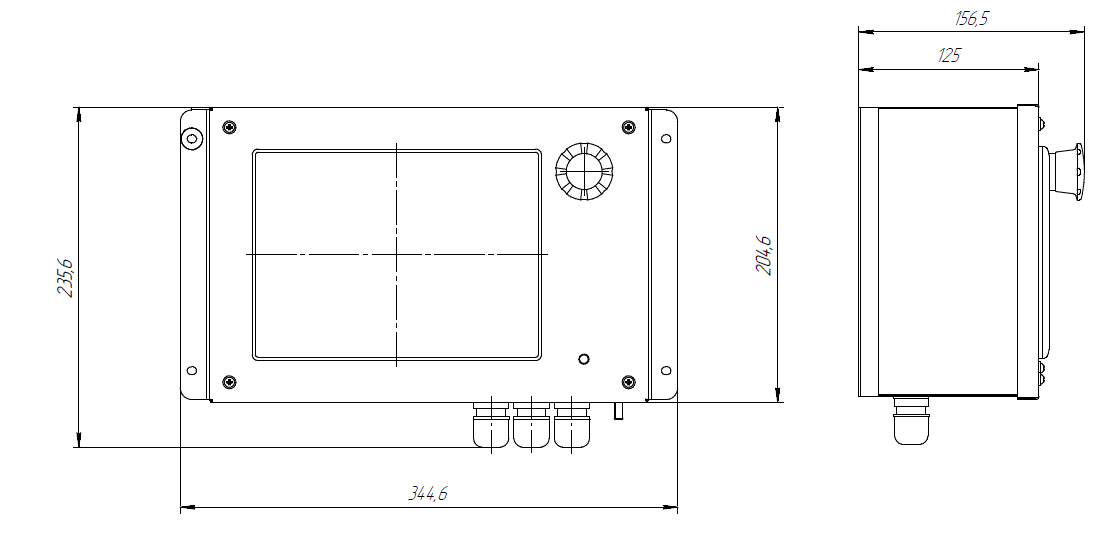
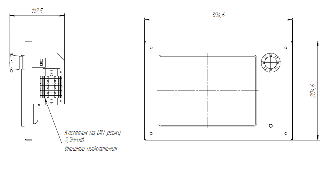
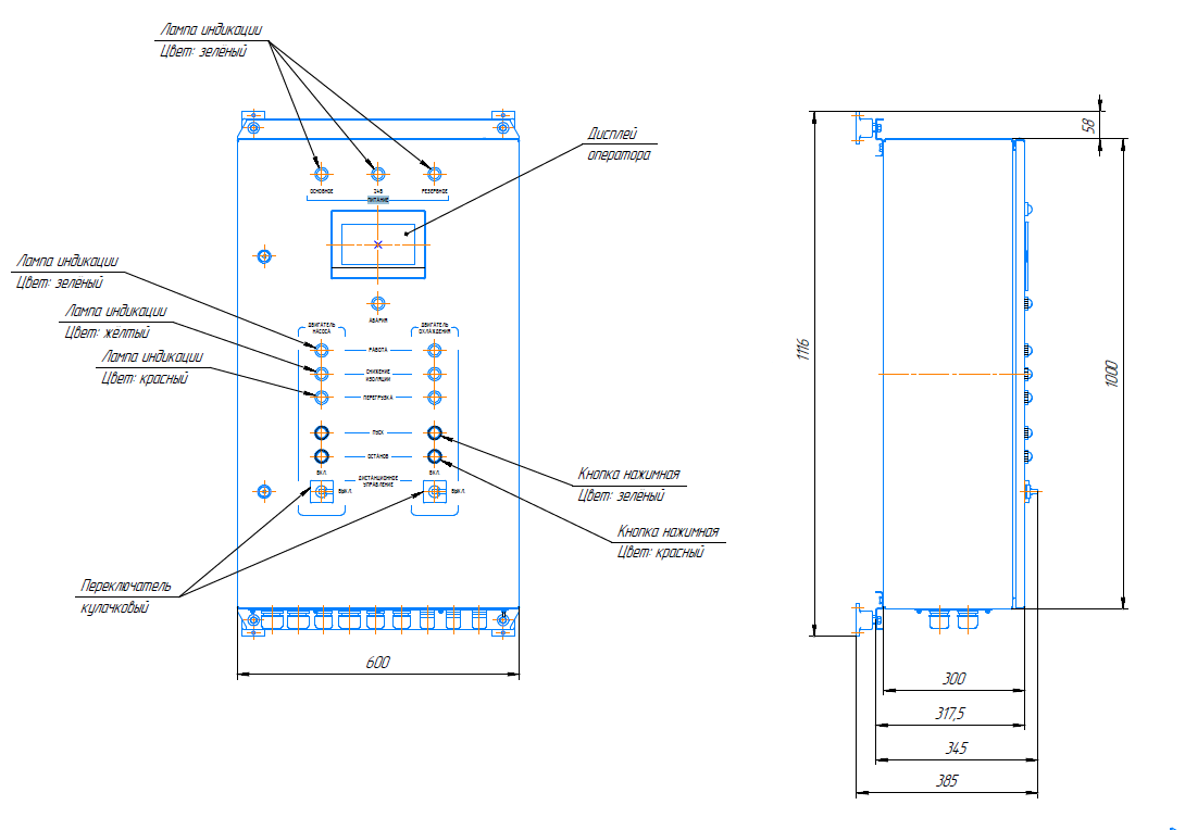
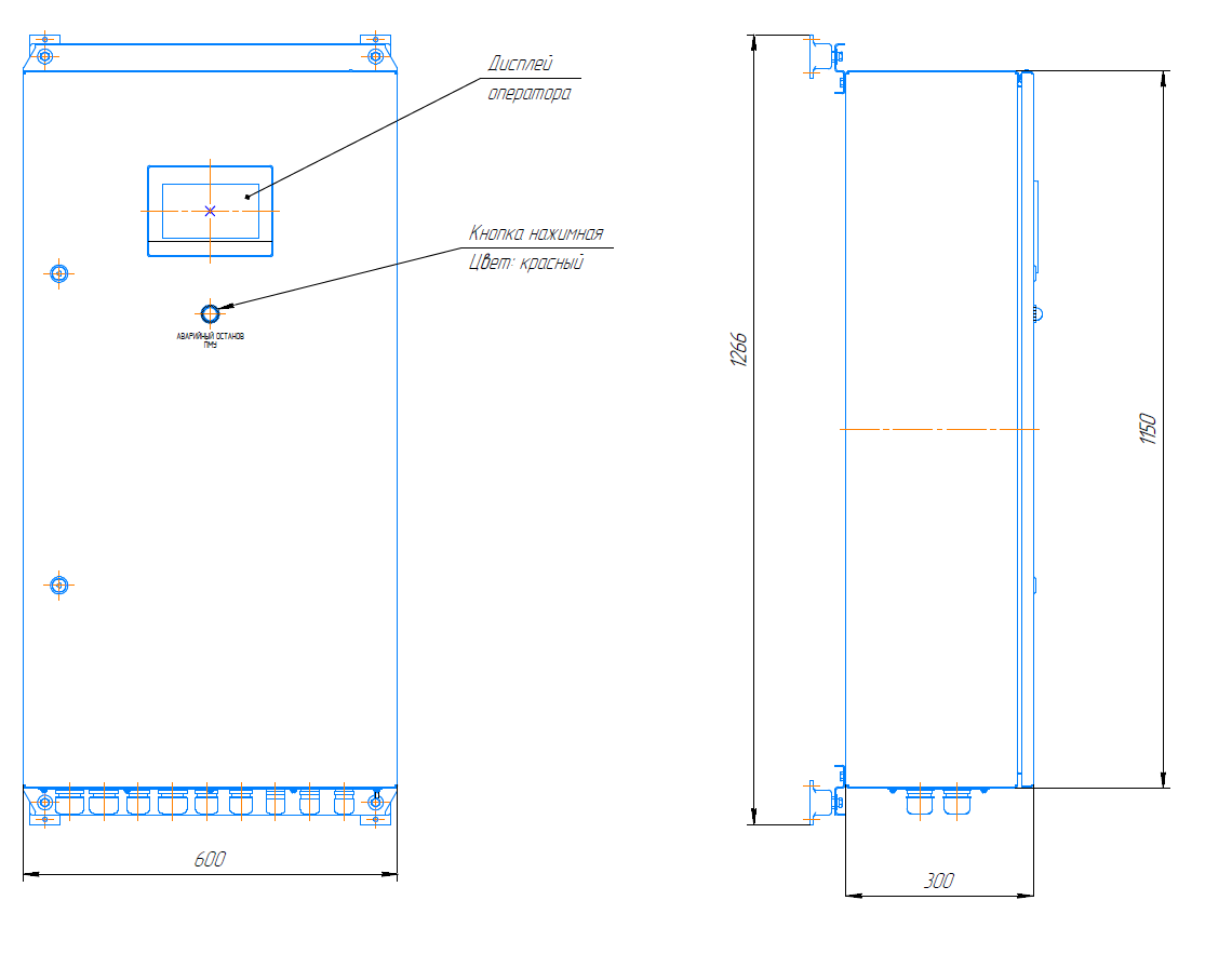
- local control device (hereinafter referred to as LCD);
- control and alarm panels (hereinafter – CAP);
- pump motor starter (hereinafter – PMS);
- rotation angle sensor (hereinafter referred to as the RAS);
- tilt angle indicator (hereinafter – TAI);
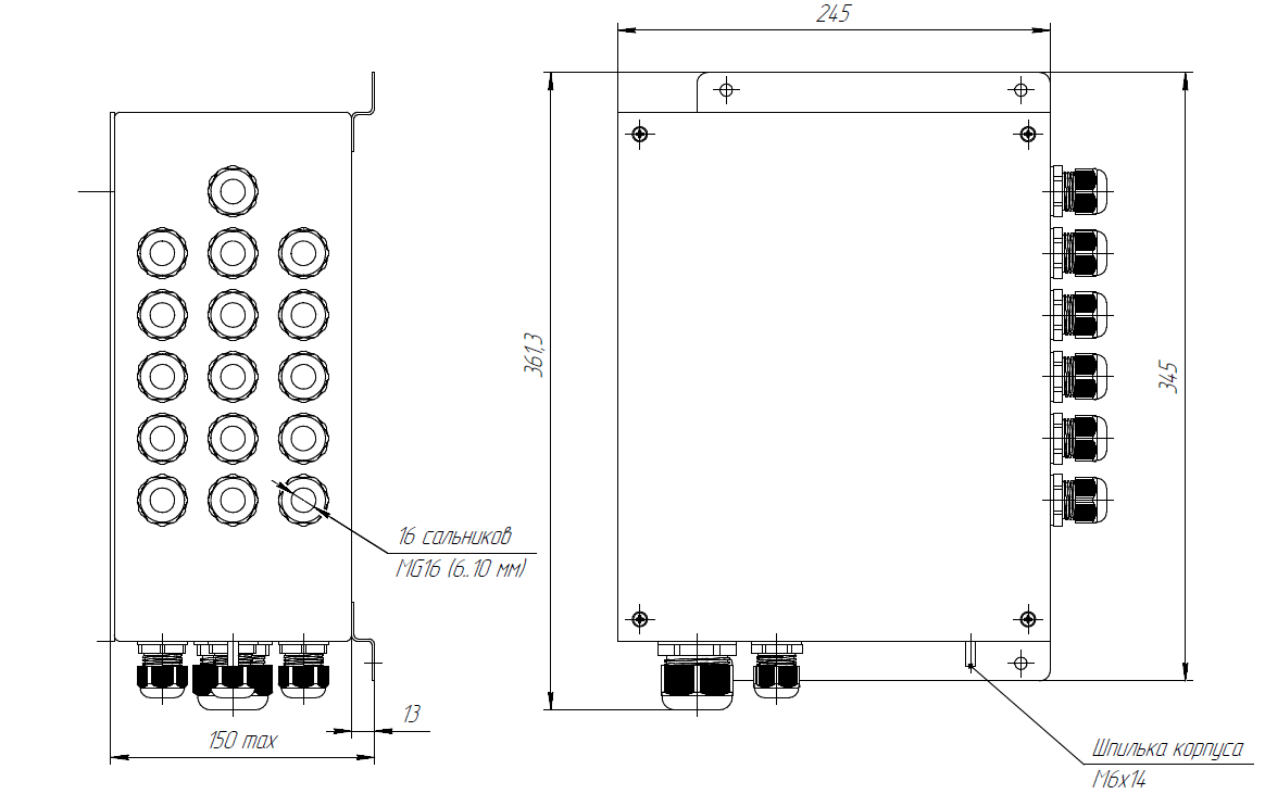
- the distribution box (hereinafter – DB).
Structural chart of the control system "SKAT-1031"
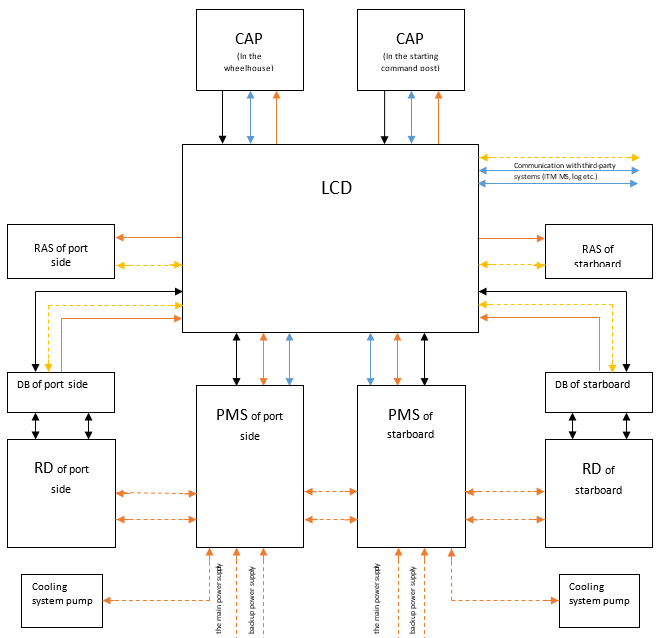
Where are indicated:
- Blocks:
LCD – local control device;
CAP – control and alarm panels;
RAS PS/SB - rotation angle sensor of port side/of starboard;
PMS PS/SB – pump motor starter of port side/of starboard;
RD PS/SB – rocking device of port side/of starboard;
DB PS/SB – the distribution box of port side/of starboard.
- Connections:
Orange dotted line – 380V power supply;
Black line – potential-free dry contacts and analog signals;
The blue line - Ethernet;
The yellow dotted line - RS-422/485.