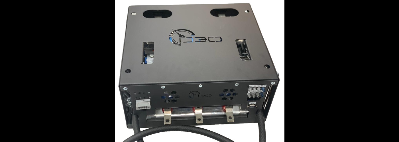
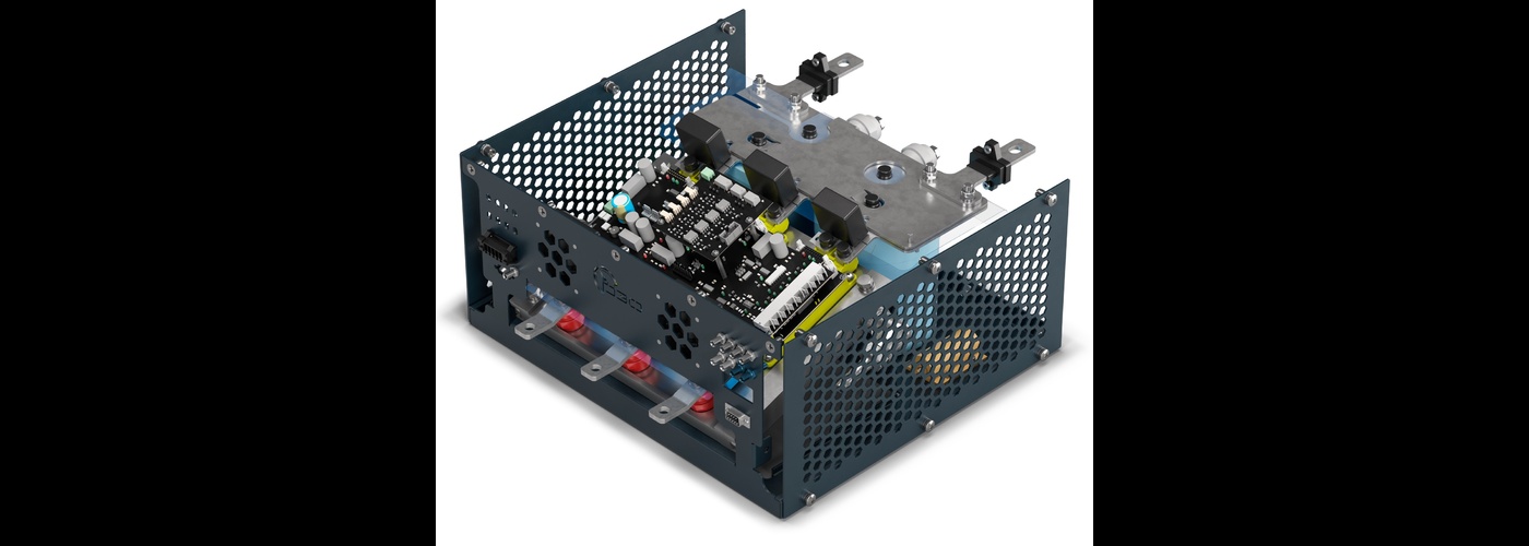
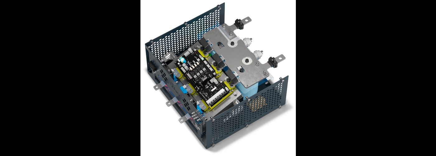
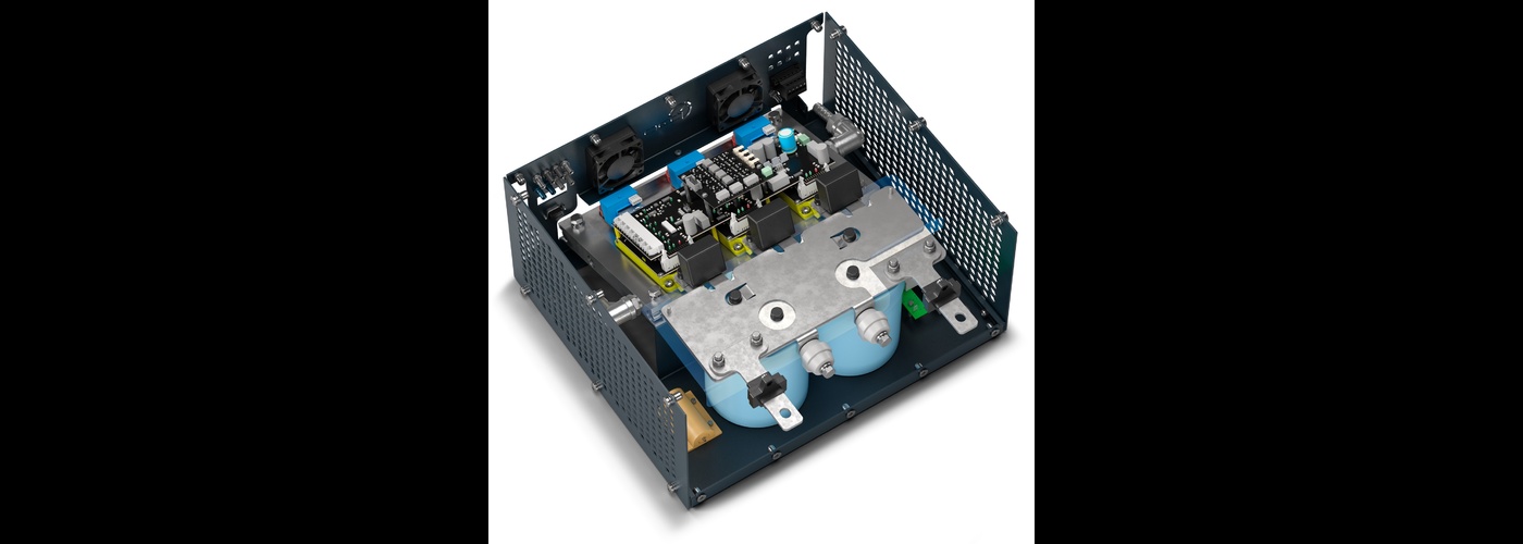
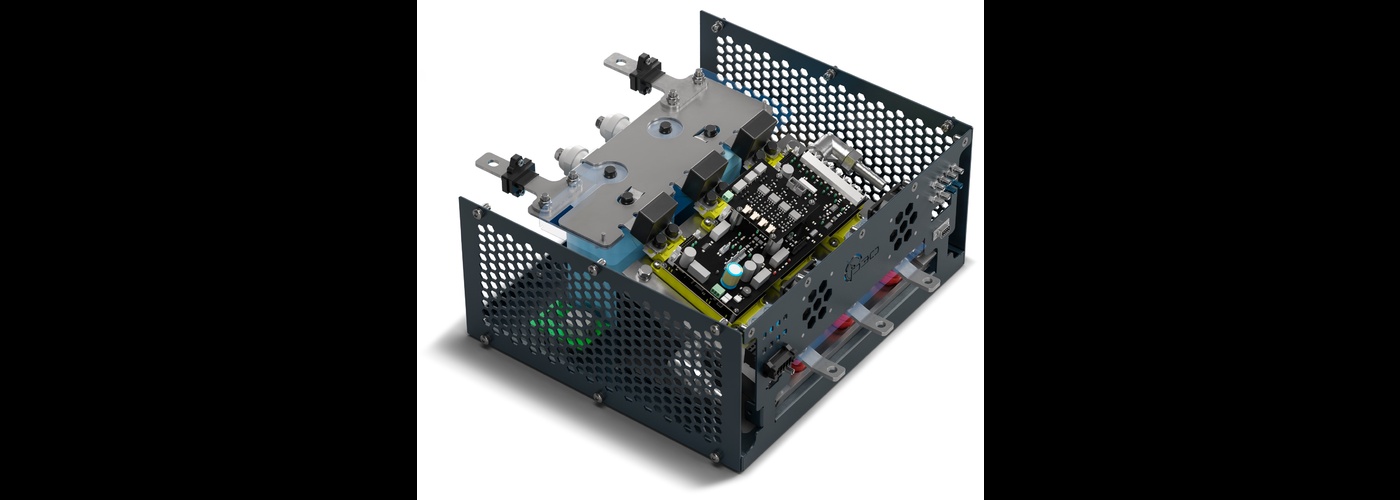
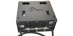
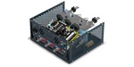
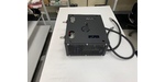
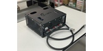
Power cell


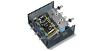

The cell is designed to be a part of power converters, e.g.:
- frequency converters;
- rectifiers;
- inverters;
- PWM controllers (DC/DC converters).
The cell ensures both bridge and differential control of the transistors.
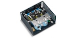
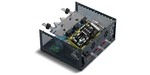
The cell combines and controls three semiconductor assemblies (modules) composed of two IGBT transistors and two inverse diodes connected via half-bridge circuit, dimensions 152*62*17 (mm) with max. voltage up to 1,700 V and rated current 600 А.
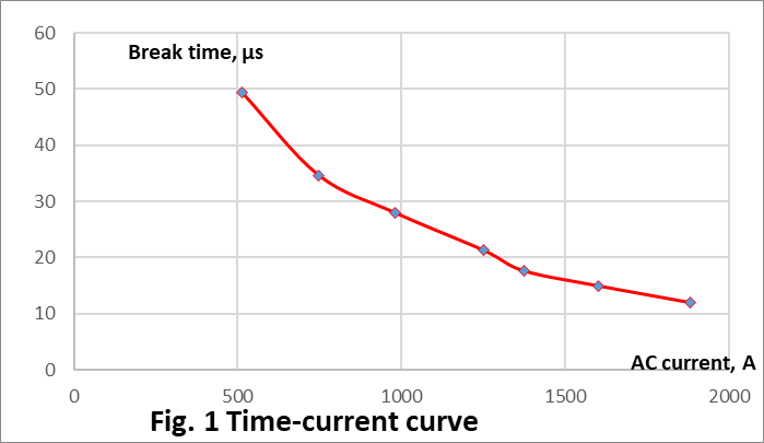
Figure 1 describes the structural diagram.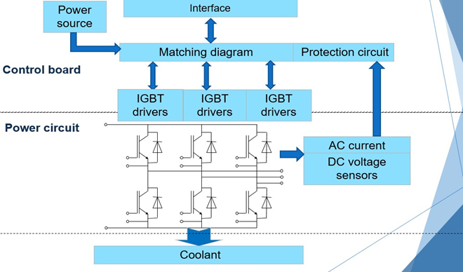
The unit belongs to NF climate category (for boreal climate) and placement category 4 (for operation indoors with controlled environment) according to Russian State Standard GOST 15150.
The power switches are controlled via a driver board. The driver board ensures:
- differential or shared control of the power switches;
- minimum on-delay of channel switching of half-bridge circuit customized (base dead time tIDT= 8 µs);
- in the event of error operation of the switches is blocked. The recovery is carried out by interruption of control signals during the pre-set customized time (base delay time tDEL= 2 ms);
- quick-acting protection of power switches in the event of emergency with break time not more than 15 µs;
- to prevent from pulse overvoltage the power equipment has soft switching on and off;
- control of transistor drivers supply voltage, low protection threshold +13.7 V. Protection switching off threshold +14.5 V;
- temperature control of the power switches;
- transmission of data on driver state and a reason of occurred error to the control system;
- galvanic isolation of signaling circuits of power equipment and control system.
The following emergencies block operation of the switches (quick-operating direct protection):
- exceeding max. switch current;
- DC bus overvoltage.
The cell tests:
100% tests: open-circuit test, rated load and short circuit under DC bus voltage 820 V.
Checks:
- functioning of the cell
- measuring of power loss in the cell
- measuring of system protection parameters
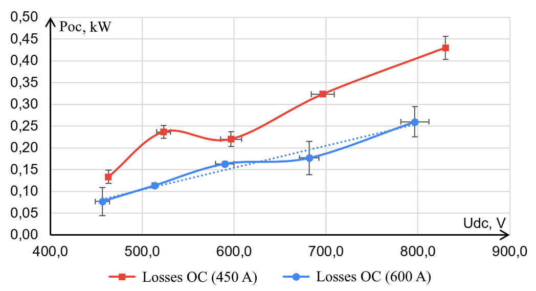
The diagrams of the test results:
Open circuit loss in the cells with transistors 450 А and 600 А:
The current and voltage diagrams under the short circuit test:
UDC – DC bus voltage (200 V/cell);
IVT – transistor current (800 А/cell);
UHLT – error signal on the driver board (2 V/cell). 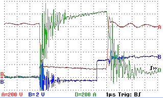
Losses under the rated current with transistors 600 А, phase distribution: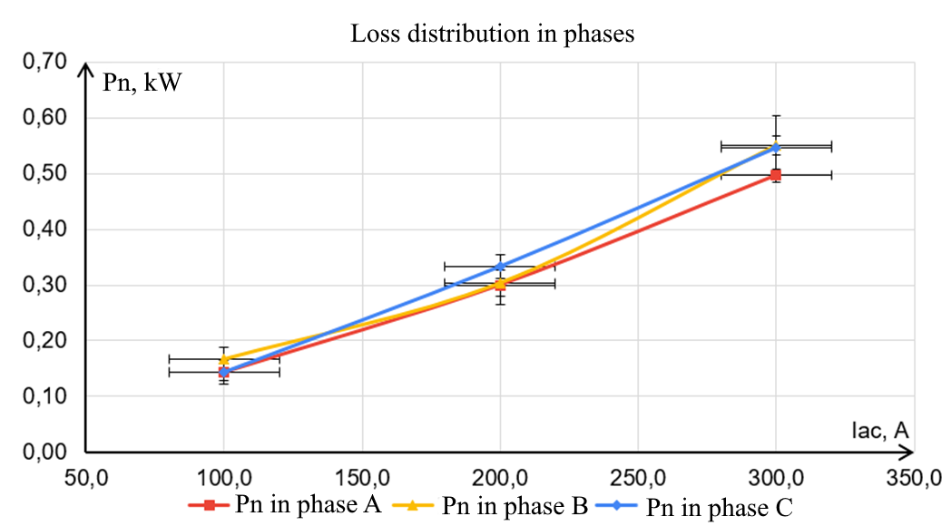
Main technical specifications of the power cell.
Model range: 100 kW, 200 kW, 400 kW.
Technical specifications, 200 kW model:
Absolute rated values
|
Identifier |
Parameter |
Value |
Units |
|
Pmax |
Total capacity |
200 |
kW |
|
IDC |
Rated DC bus current |
250 |
А |
|
VDC |
Rated DC bus voltage |
800 |
V |
|
IAC |
Rated AC bus current |
310 |
А |
|
UAC |
Rated AC bus voltage |
380 |
V |
|
tDT |
Set dead time |
8 |
µs |
Absolute maximum values
|
Identifier |
Parameter |
Value |
Units |
|
VDC MAX |
Max. DC bus voltage |
950 |
V |
|
IAC MAX |
Max. AC bus current (rms) |
350 |
А |
|
tVT MAX |
Max. temperature of transistor module |
100 |
˚С |
|
fPWM MAX |
Max. PWM frequency |
5 |
kHz |
Main technical specifications
|
Parameter |
Comments |
Value |
Units |
|
Efficiency |
min. |
95 |
% |
|
Heat losses |
Under rated АС current and PWM frequency 2 kHz, max. |
2 |
kW |
|
Operating conditions |
|||
|
Climate category |
|
NF4 |
|
|
IP |
Level of moisture and dust protection |
IP10 |
|
|
Cooling |
|
Water |
|
|
pW MAX |
Max. water pressure in the coolant circuit |
106 |
Pa |
|
tW MAX |
Max. water temperature in the coolant circuit |
40 |
˚С |
|
Height |
Above sea level, max. |
1000 |
m |
|
Interface |
|||
|
Control |
To the cell |
Optics, Broadcom |
|
|
Error signal |
From the cell |
Optics, Broadcom |
|
|
Signals from sensors |
Electric analog |
Current, 0-20 mA |
|
|
Design specifications |
|||
|
Dimensions |
|
475 х 440 х 210 |
mm |
|
Weight |
Max. |
16.5 |
kg |
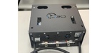
Description of the front panel connectors
|
XT1 |
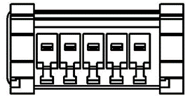 |
PIN |
Description |
|
1 |
Digital power supply 24V+ |
||
|
2 |
Digital power supply 24V- |
||
|
3 |
Field power supply 24V+ |
||
|
4 |
Field power supply 24V- |
||
|
5 |
Grounding |
||
|
DC power connector |
|||
|
XT2 |
 |
PIN |
Description |
|
1 |
UDC + |
||
|
2 |
UDC - |
||
|
3 |
IAC1 + |
||
|
4 |
IAC1 - |
||
|
5 |
IAC2 + |
||
|
6 |
IAC2 - |
||
|
7 |
IAC3 + |
||
|
8 |
IAC3 - |
||
|
9 |
N/C |
||
|
Current analog output connector from sensors 0-20 mA according to GOST 26.011-80 |
|||
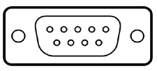
|
XS1-XS8 |
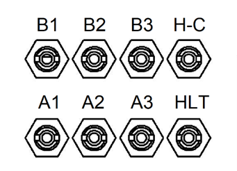 |
PIN |
Description |
|
A1 |
Signal receiver Top1 |
||
|
A2 |
Signal receiver Top2 |
||
|
A3 |
Signal receiver Top2 |
||
|
B1 |
Signal receiver Bot1 |
||
|
B2 |
Signal receiver Bot2 |
||
|
B3 |
Signal receiver Bot3 |
||
|
H-C |
Transmitter of error code signal |
||
|
HLT |
Clock signal transmitter, error signaling unit |
||
|
Optical connectors HFBR-0500 |
|||
Design features:
- fluid- (water, anti-freeze solution) and air-cooled units;
- IGBT transistors;
- optical control interface;
- enhanced protection system.
The cell protects against the following emergency operation modes:
- short circuit in the load circuit AC – when the current in AC circuit increases by more than 120% from the rated current (see fig. 1);
- exceeding voltage drop across an open switch (more than 8 V, see fig. 2);
- DC bus overvoltage;
- power switch over temperature;
- driver or IGBT module failure.